

Long range gps jammer l1- l5 | purchase gps jammer threat
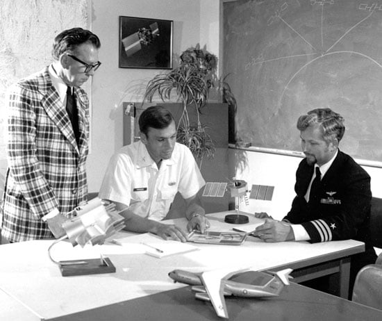
Five Challenges, One Key Technology, the Political Battlefield — and a GPS Mafia Part 2 of a Two-Part Story. Read Part 1 here. By Bradford W. Parkinson and Stephen T. Powers, with Gaylord Green, Hugo Fruehauf, Brock Strom, Steve Gilbert, Walt Melton, Bill Huston, Ed Martin, James Spilker, Fran Natali, Joe Strada, Burt Glazer, Dick Schwartz, Len Jacobson, AJ Van Dierendonck, and others. GPS Phase I program approval meant that the real work could begin. The conclusion of a two-part history, told by the people who made it. By January 1974, the GPS program at the Joint Program Office (JPO) was well underway. With only about 30 officers, the workload was enormous. Fortunately, the Aerospace cadre of about 25 also made extraordinary contributions. In a flurry of activity, the team developed requests for proposals, made top-level specifications, and published initial interface control documents. The work of converting viewgraphs into real hardware, as many know, is an exacting and sometimes painful process. Of course there were many challenges, but five of them, principally engineering, stand out as particularly daunting. These were: Defining the specific details of the GPS CDMA signal structure; Developing space-hardened, long-life, atomic clocks; Achieving rapid and accurate satellite orbit prediction; Ensuring and demonstrating spacecraft longevity approaching ten years; Developing a full family of GPS user equipment. We discuss each challenge in detail, including the names of those most instrumental in meeting them. The first appearances of their names are highlighted, although if they appeared in Part 1 of this story (May 2010 issue), their names are not highlighted. EARLY GPS MANPACK worn by JPO Army deputy Lt. Col. Paul Weber. This photo graced the cover of the first-ever GPS brochure! (Credit: Bradford W. Parkinson and Stephen T. Powers) Challenge 1. Defining the specific details of the GPS CDMA signal structure (coherence, acquisition, spreading, communication protocol, structure, error correction, message structure, and so on). The selection of the GPS signal structure was broadly confirmed with the tests that were run by program 621B at the White Sands Missile Range with the help of Joe Clifford, Bill Fees, and Larry Hagerman, all from the Aerospace Corporation. While the fundamental decision to select CDMA had been made during the Lonely Halls meeting, a vast number of details had yet to be worked out. Fortunately, there were many earlier studies of the signal. Dr. Jim Spilker (then of Philco Ford), who had also written the major reference book on digital communications, authored one of the studies. Dr. Charles Cahn, Nat Natali, Burt Glazer, Ed Martin, and Dr. Robert Gold of Magnavox all made significant contributions. One of the most important details was the decision that the carrier, code, and data of the GPS signal would all be phase-coherent (Figure 1). As discussed later, this decision enabled much of the precision that we now see in advanced GPS receivers. FIGURE 1. GPS signals were designed to be all aligned as transmitted, that is, coherent. (Courtesy Misra and Enge, Global Positioning System). The exact Gold codes family had to be selected from the original family, since Dr. Gold’s technique did not include the natural Doppler shifts. The data message was integrated into both the civil (C/A ) and military (P/Y) signals through inversion of their codes every 20 milliseconds. To work out the details of the data message, the JPO had a strong team including Major Mel Birnbaum, Col. Brock Strom, and Capt. Bob Rennard. Outside contractors making major contributions included Dr. Fran Natali, Dr. A. J. Van Dierendonck, and others. Van Dierendonck played a particularly effective role in helping define “GPS time.” This sounds rather mundane, but had some very interesting complexity. Jim Spilker recommended the 1023-bit message length to avoid a correlation problem associated with Doppler shifts (this recommendation was incorrectly attributed in the last issue). The data stream came down at 50 bits per second. Through this tiny pipe of information, all the precision of GPS had to pass. It included the space-vehicle orbit-position information (ephemerides), system time, space-vehicle clock-prediction data, transmitter status information, and C/A signal handover time to the P/Y code. Also as a part of the message, ionospheric-propagation delay models were incorporated for the single-frequency user. Further, to aid rapid acquisition of new satellites just rising over the horizon, the ephemerides of all other satellites in the full constellation had to be included. Each digital word had to be defined in terms of scaling, bias offset, and precision in terms of the number of bits transmitted. About 95 percent of the GPS message has endured with no changes needed at all. In a few cases, because the newer user equipment is more accurate, greater precision is desirable. It is a great tribute to the brilliant engineers and scientists who designed the signal structure in 1975 that it has endured for 35 years with so little need for modification. Some of the JPO Heroes at a “dining-in,” a recognition dinner. From left, Major Mel Birnbaum (made many important contributions. He was famous for marathon code reviews that could last 18 hours straight. He hated to miss schedules!); Col. Don Henderson (later Maj. Gen.) second Air Force deputy; Major Ralph Tourino (later Maj. Gen.), Program Control; Lt. Col. Ken Juvette. director of procurement; and LCdr. Joe Strada, a key leader in the extensive test program. (Credit: Bradford W. Parkinson and Stephen T. Powers) Credit: Bradford W. Parkinson and Stephen T. Powers Challenge 2. Developing space-hardened, long-life, atomic clocks (qualified for the upper Van Allen Belt, with 4- to 5-year lifetime requirement for individual clocks). In 1966, both the Air Force and the Navy recognized that developing a precise, stable time-base for generating the one-way (passive) navigation ranging signal in the satellite was essential. Cesium atomic clocks had been invented, demonstrated, and offered for commercial sale by the middle of the 1950s, before the Space Age. The major commercial issues with these clocks were that they tended to be bulky, power-hungry, and not hardened against space radiation. To address that problem, rubidium atomic clocks, noteworthy for their small size and low power requirements, were developed. Still, the issues of mechanical and radiation hardening as well as temperature sensitivity had to be resolved before they could be used in space. The 621B/Woodford/Nakamura study of 1964/66 called for atomic clocks in the satellites in at least seven places. The study advocated a technology program to space-harden existing clock technology. Unfortunately, the Air Force chose not to pursue a space atomic-clock technology program. However, the Naval Research Laboratory (NRL) did institute a program in 1964. It pursued the technology for stable clocks with a series of satellites that have already been discussed. The first Timation satellite, launched in May 1967, carried a quartz clock. Not surprisingly, the frequency varied substantially with satellite temperature. The second Timation satellite also contained a quartz clock as well as a temperature controller and showed improved operation, but the results still fell short of those necessary for a GPS satellite. The third satellite in the series had not been launched before the Pentagon approved GPS development in December 1973. In any case, Timation 3 was designed to carry two slightly upgraded, off-the-shelf commercial rubidium clocks. Qualification Model of the first GPS atomic clock, built by Rockwell International working directly with Efratom, a small German company. (Credit: Bradford W. Parkinson and Stephen T. Powers) Based on the progress that NRL had made, during the Lonely Halls meeting the JPO decided to commit to atomic clocks in the first operational GPS satellites. This third Timation satellite was renamed NTS-I and came under the newly formed Joint Program Office for GPS. The satellite was launched on July 14, 1974, as a part of the GPS program. However, the ineffective attitude-stabilization system caused varying sun angles and hence, significantly varying temperatures, masking any careful evaluation of the rubidium performance. The GPS space-based rubidium atomic clock technology was derived from a unit produced by Efratom, a small company initially based in Germany. The geniuses behind this creative device were Ernst Jechart and Gerhard Huebner. By the summer of 1974, a satellite contractor, Rockwell International (RI), had been selected to build the GPS operational satellites. Included in the program direction by the JPO was a separate development of rubidium clocks for the satellites as an alternative to the NRL cesium clock effort, in case the NRL effort faltered. Hugo Fruehauf of Rockwell had independently discovered and contacted Efratom, the company that NRL was working with, although his interaction was totally independent of that of the NRL. In addition, Fruehauf’s relationship with Efratom was simplified because of his fluency in German, since Jechart did not speak English, and Efratom had just established an office in Southern California near the Rockwell developers. Figure 2, a page from the original Rockwell proposal, shows the excellent ground test data at both 1000 seconds and at 24 hours. Figure 2. Test results for the Rockwell proposed GPS space-hardened prototype atomic (rubidium) clock, based on the Efratom commercial clocks. (Credit: Bradford W. Parkinson and Stephen T. Powers) On realizing that the small Efratom company would be incapable of producing a radiation-hardened, space-qualified rubidium oscillator, RI’s GPS satellite program manager Richard Schwartz created a teaming relationship with them, which included his chief engineer, Hugo Fruehauf, plus Dale Ringer, Dr. Chuck Wheatley of Rockwell’s Autonetics Division, and Efratom’s Werner Weidemann. With heroic efforts, this team built a space-qualified clock in time for the first GPS launch in February 1978. Meanwhile, the NRL-sponsored development of a cesium clock by FTS ran somewhat behind schedule. Their cesium clock was not available for the first three GPS satellite launches. The first NRL hardened clock was included on the fourth GPS satellite; unfortunately that unit failed after 12 hours of operation because of a power-supply problem. As a result, the only operating clocks on the first four GPS satellites were those developed by the Joint Program Office through its contractor Rockwell International. The decision to proceed to full-scale development for GPS, called DSARC 2, was made before any NRL-developed clocks had become operational. That said, the NRL-sponsored FTS cesium clocks were available for later satellites, and performed extremely well. Later Block II GPS satellites carried two rubidium-frequency standards made by Rockwell and two cesium-frequency standards (primary source, Frequency and Time Systems; secondary sources, Kernco and Frequency Electronics Inc., on selected vehicles). Figure 3 summarizes the early clock program. Figure 3. Earliest satellite-clock technology developments, culminating in the last row: four Rockwell satellites with Rockwell-developed rubidium clocks. (Credit: Bradford W. Parkinson and Stephen T. Powers) In spite of NRL’s development difficulties, GPS users owe a debt to the lab for its pursuit of this technology. Clearly GPS would not have performed so well without space-hardened atomic clocks. It was the apparent NRL progress that strengthened the argument. The support of Ron Beard of NRL in this joint effort has been invaluable to the program over many years. More than 450 atomic frequency standards have now flown in space. By far the greatest user has been GPS. Challenge 3. Achieving rapid and accurate satellite orbit prediction, to within a few meters of user ranging error (URE) after 90,000 miles of travel. Since the GPS system architecture had upload stations only on U.S. soil, the satellites were out of sight for many hours, making accurate prediction of their orbits essential. To achieve the expected positioning accuracy, the orbit prediction had to contribute less than a few meters of ranging error after 90,000 miles of travel. Achieving this standard was a major challenge in the early days of GPS. Such a prediction must account for the complications of Earth pole wander, Earth tides, general and special relativity, the noon turn maneuver of the satellite, solar and Earth radiation, and the reference station’s location. Figure 4 gives an example of the problems of polar wander.With roughly a 400-day period, this effect had an amplitude of many tens of feet. While this wander has to be included in the GPS orbit-prediction model, fortunately GPS is the major technique to measure it. Another, usually unrecognized feature is that the monitor stations only use the GPS signal for ranging. In other words, they are passive, rather than using the usual technique of that era, two-way ranging. The reference receivers were of a special design, developed by Jim Spilker’s company, STI. They successfully received the first signal from the Rockwell/ITT satellite (NDS-1) on March 5, 1978, after its launch on February 22, 1978. Fortunately, the Transit program had pioneered precise orbit prediction and had taken these effects into account. Its Astro/Celeste program, developed by Bob Hill and Dick Anderle at the Naval Surface Weapons Center in Dahlgren, Virginia, batch-processed the measurements taken by the reference stations. Unfortunately, this processing would take too long to provide the most up-to-date predictions. A new scheme was devised that included partial derivatives of prediction relative to reference-station measurements. A.J. Van Dierendonck applied his knowledge of filters to help lead development of these calculations, which allowed a modified (linearized) Kalman filter to be used for near-real-time optimal prediction. Bill Fees of Aerospace, Walt Melton of General Dynamics, and Sherm Francisco of IBM, among others, implemented these techniques. The initial master control and upload stations were located at Vandenberg Air Force Base, since moved to Schriever Air Force Station; a backup master control station has been re-established at Vandenberg. Figure 4. Motion of the Earth’s spin axis must be included in the measurement parameters for GPS satellite location. The broadcast ephemeris is adjusted to include this effect, so the user need not make further adjustments. (Courtesy of International Earth Rotation and Reference Service). (Credit: Bradford W. Parkinson and Stephen T. Powers) Challenge 4. Ensuring and demonstrating spacecraft longevity approaching 10 years (the issue was GPS affordability) The issue was simply that sustaining a constellation of 24 satellites would be prohibitively expensive if the satellites did not have long lives. Again, the Air Force/621B study by Woodford and Nakamura in 1966 focused on the problem: “The most specific change in satellite technology is the increase of mean time before failure (MTBF). MTBFs on the order of 3 to 5 years can now be considered feasible.” The problem is easily illustrated in Figure 5. The light blue line shows the trade-off between average satellite lifetime, L, and the required number of satellites per year for a 24-satellite constellation. GLONASS, the Russian system competing with GPS, has the experience shown in the upper white box. With satellite lifetimes averaging two to three years (or less), GLONASS has a corresponding requirement for eight to 12 satellite launches per year. Only a very wealthy country can sustain such a launch program. Figure 5. The imperative for long satellite lifetimes. (Credit: Bradford W. Parkinson and Stephen T. Powers) The red oblong illustrates the U.S. GPS experience, which requires only two to three launches per year. Also shown is the initial experience of GPS during Phase I. The first 10 GPS satellites reached an average age of 7.6 years, with #3 and #10 exceeding 9 years. This is an enormous credit to Rockwell International and in particular the program manager Richard Schwartz. He had excellent system engineering support from Andy Codik. The JPO satellite division was intially led by Major Gaylord Green and later by Maj. Doug Smith, with help from Capt. Jack Henry. Three factors are key to long-lived satellites: Designs with carefully selected redundancy (for example, clocks, power amplifiers), Enforcing a rigorous part-selection program including the de-rating of parts (must be class S. or equivalent), Testing as you fly and insisting on a detailed analysis of all failures. Figure 5 also illustrates why the Timation clocks could not be used as prototypes for the GPS program. In general, their maximum lifetimes were approximately one year. Clearly their designs needed greater maturation. The demonstrated lifetimes were essential to passing the next milestone, DSARC II, which allowed GPS to proceed to full-scale development. Challenge 5. Developing a full family of GPS user equipment that capitalized on the digital signal (leading to inexpensive digital implementation) and spanned most fundamental military uses, as well as demonstrating civilian cost feasibility. The last, but certainly equally difficult of these five engineering challenges, was the development of nine different types of GPS user equipment. Recognize that a major part of the challenge was to stuff the real-time digital software processing into the relatively primitive digital computers of that era. Table 1 summarizes the development of user equipment: Data: Bradford W. Parkinson and Stephen T. Powers All of the sets performed well within specification. They were characterized, however, by large size and heavy power demands. Magnavox, under the technical direction of Vito Calbi, produced the largest variety of user equipment. It was a subcontractor to General Dynamics, who reported directly to the JPO. At Aerospace, Frank Butterfield was a gifted contributor, particularly skilled at practical antenna design. The Generalized Development Model (GDM) reciever, developed by Rockwell Collins Group, was the largest of the sets, created for a specific purpose: to demonstrate the ultimate jam resistance for GPS user equipment. It attained performance better than 100 db jamming-to-signals ratio (J./S) in actual flight test. The GDM receiver achieved this by integration with inertial components, directional antennas, and shading with the aircraft body. Such a receiver can fly directly over a 1 kW jammer at 4,000 feet and not be affected. The original GDM program manager at the USAF Avionics Lab was Maj. Roger Brandt. The Rockwell Collins Generalized Development Receiver (GDM). This advanced receiver achieved more than 100 dB of anti-jam in actual flight tests. (Credit: Bradford W. Parkinson and Stephen T. Powers) The single-channel manpacks were large and clumsy, but they operated very well. The payoff created by the CDMA signal is illustrated with the 12-channel, single-chip modern implementation, shown in the bottom picture. This contemporary chip’s accuracy is much better than any of the equipment produced during Phase I. Developing test environment and analysis setup was almost as challenging as the user equipment. Lt. Col. Val Denninger, Maj. Darwin Abbey, and Lt. Cdr. Joe Strada led this very successful effort. While most testing took place at Yuma Proving Ground, test sites were also located in San Diego and elsewhere. Left: 1978 single-channel (sequential) Manpacks, two types by Magnavox and Texas instruments. Batteries alone weighed much more than current military handsets. Right: The second JPO deputy, Col. Don Henderson (left), and Aerospace program manger Ed Lassiter (right). Bottom: A modern 12-channel (parallel) Atheros chip receiver with more capability. (Credit: Bradford W. Parkinson and Stephen T. Powers)" width="550" height="302" />Left: 1978 single-channel (sequential) Manpacks, two types by Magnavox and Texas instruments. Batteries alone weighed much more than current military handsets. Right: The second JPO deputy, Col. Don Henderson (left), and Aerospace program manger Ed Lassiter (right). Bottom: A modern 12-channel (parallel) Atheros chip receiver with more capability. (Credit: Bradford W. Parkinson and Stephen T. Powers) The Most Fundamental GPS Innovation The CDMA (spread-spectrum or PRN) modulation used for passive ranging is clearly the most fundamental innovation of GPS. This signal enabled four-dimensional positioning for the user without requiring an atomic clock in the user equipment. The Russian GLONASS (the other, partially-operational global navigation satellite system) also used spread-spectrum passive ranging, but resorted to a frequency-separation scheme (FDMA, frequency-division multiple-access) that has proven inferior in actual use. The innovative design of this CDMA signal has enabled all of today’s precision applications for GPS. It is currently common for inexpensive GPS receivers to simultaneously receive signals from more than 10 satellites, yet all of these signals are being broadcast on exactly the same frequency. In fact, the number of signals that can be received is virtually unlimited using the spread-spectrum CDMA approach. Using a routine processing algorithm, the user, receiving more than four signals, has an instantaneous position that is more accurate than that using four satellites alone. This robustness includes a technique to ensure integrity of the GPS solution. The method, called receiver-autonomous integrity monitoring (RAIM), isolates a rogue satellite that is not operating properly, to ensure integrity of the GPS solution. Another technique, called carrier tracking, is enabled with the coherence of the code and the carrier broadcast in this signal. When coupled with some form of differential GPS operation, the result is relative positioning accuracy that is unprecedented — frequently better than a millimeter. For example, surveyors can now routinely resolve three-dimensional position to this accuracy. Even common user equipment can make use of the coherence of the signal. The receiver accomplishes this by employing the so-called Hatch/Eschenbach filter that uses the reconstructed carrier signal to smooth the code-transition measurement that greatly decreases the noise of the raw code measurement. The processing gain in the GPS CDMA signal has been enhanced by deep integration with inertial navigation components. This has enabled the demonstrations of very high interference rejection by such receivers. Dale Klein and Ed Copps of Intermetrics Corp. were major contributor s to the integration of GPS with inertial measurement units for the Magnavox high-performance military receivers. Side-Tone Ranging. The competing side-tone ranging signal structure offered by NRL in the 1970 Easton patent had a fundamental flaw. If the signals were broadcast at the same frequency, they would interfere with each other. On the other hand, if they were broadcast on different frequencies, the user equipment would require a separate analog front end and tracking loops for each signal. In addition, each channel would have its own time-delay bias that would probably vary with temperature of the user equipment. A study by Magnavox also noted that the side-tone ranging signal could be easily spoofed; it was not clear how to encrypt such a signal. The final problem was that the signal was fundamentally an analog type and would have not been able to take advantage of modern digital signal processing. As a result, the receivers would be more complex and expensive. The Air Force 621B/Aerospace and Magnavox studied the CDMA signal structure extensively after the 621B Woodford/Nakamura study was completed in 1966. Bob Gold of Magnavox had, in 1967, invented the technique to select acquisition codes that were mathematically guaranteed to not look alike (were uncorrelated). Early in the program, the JPO hired Dr. Jim Spilker, a recognized worldwide authority on digital signal processing, to contribute to this effort. Another worldwide expert, Charlie Cahn of Magnavox, was also a major contributor to the signal design. As mentioned previously, the details of the signal required the efforts of many people. By 1969, the CDMA signal was being used in many communication applications. Adapting this signal for navigation raised the questions that were posed in an earlier section. It is hard to believe today the issues surrounding its use had to be addressed in 1970. It is to the great credit of Program 621B that it built the receivers and ran the series of tests at White Sands Missile Range that had earlier resolved all the major issues surrounding the signal structure. This irrefutable evidence allowed the JPO team to confidently choose this signal during the Lonely Halls meeting in September 1973. Great credit must go to Bill Feess who worked tirelessly to complete the analysis that demonstrated 5-meter accuracy in those White Sands tests. CDMA-Enabled Applications The distinction between the Timation side-tone ranging and the 621B CDMA signal is critical to understanding the origins of GPS. The Air Force CDMA signal was different in essential and fundamental ways from the Easton side-tone ranging modulation. Three examples of precise three-dimensional applications, not achievable with side-tone ranging, illustrate the subsequent success of the 621B digital CDMA signal. Aircraft Blind Landing. In 1992, the Federal Aviation Administration (FAA) sponsored Stanford’s development and demonstration of the first Category III (blind landing) system in a commercial aircraft; the effort was led by Clark Cohen and developed by a group of Stanford students under the supervision of Brad Parkinson. The only sensor for both position and attitude was GPS. The carrier-tracking receiver was a derivative of a Trimble receiver; it relied on the CDMA signal structure for both accuracy and integrity. (See Figure 6.) Figure 6. Results of first blind landing tests using GPS alone, 110 landings with a commercial Boeing 737. (Credit: Bradford W. Parkinson and Stephen T. Powers) Robotic Farm Tractor. Using similar technology, a different group of Stanford students in the same lab demonstrated the first precision GPS-controlled robotic farm tracker. Again, the capability was enabled by the GPS CDMA signal. The John Deere Company sponsored this effort, which has now expanded into a worldwide market of more than $400 million per year. Robotic farm tractor developed at Stanford with support from John Deere company. Student leader Mike O’Connor and colleague Tom BeLl shown. Tracking test at 5 meters/second, with worst error around 3 inches! Now a $400M/year market. (Credit: Bradford W. Parkinson and Stephen T. Powers) Earth Crustal Monitoring. A third example of the power of the CDMA signal is precise survey, focused on Earth movement and crustal tracking (Figure 7). The original GPS surveying receivers were pioneered by Phil Ward at Texas Instruments and Charlie Trimble at Trimble Navigation, among others. Figure 7. Continuous observation of earth crustal motion with a precision of better than a millimeter: distributed slip on Kilauea volcano, Hawaii. (Credit: Bradford W. Parkinson and Stephen T. Powers) Summary. Many technologies came together to make GPS operational, none more revolutionary than the signal structure demonstrated by 621B at White Sands, and selected by Parkinson during the Lonely Halls meeting. Virtually all high-precision uses of GPS depend on the characteristics of this signal. Credit: Bradford W. Parkinson and Stephen T. Powers More on GPS Origins The fundamental basis for the GPS design was clearly the Woodford/Nakamura and subsequent studies undertaken by 621B, not the system outlined by NRL in the Easton patent. More than 500 million current users have overwhelmingly confirmed the value of the selected technique using a minimum of four-satellite passive ranges and the CDMA signal. If each GPS user had to employ an atomic clock, the price of most GPS receivers would be prohibitive. The value of a four-dimensional solution for users has also been irrefutable. Had GPS followed the blueprint of the NRL patent, it is reasonable to say that almost all system uses, military as well as civilian, would have been fatally compromised. Further, had the Easton side-tone ranging signal been selected, broadcasting 30 satellites on the same frequency, as GPS does today, would have created an undecipherable electromagnetic jumble. Summarizing Easton’s Patent. We earlier mentioned the NRL/Easton patent for the Timation design. It is important to summarize that invention and its relationship to the actual GPS design. A few people have written that Roger Easton “invented” GPS. As stated, Easton did have a competing concept that he had developed at NRL. In October 1970, four years after the completion of the secret, seminal system study by Woodford and Nakamura, Easton applied for a patent, “Navigation System Using Satellites and Passive Ranging Techniques,” that was granted on January 29, 1974 (U.S. 3,789,409). A careful reading of the patent, available on the web, reveals the following: The technique described by Easton clearly calls for a synchronized “extremely stable oscillator” at the user station. Elsewhere he states: “would typically be controlled by an atomic clock.” This less-capable method of navigating was examined in the Woodford/Nakamura study, four years before Easton’s patent application, and is definitely not the technique chosen by GPS. The patent advocates the use of a passive ranging technique, whose description occupies most of the patent, with multiple frequency tones, not the CDMA technique of GPS that had already been studied by 621B. Before the patent was issued, 621B had already built prototype GPS CDMA receivers, flown them at the White Sands range, and demonstrated three-dimensional accuracies of about 5 meters. The Easton passive-ranging technique, commonly called side-tone ranging (STR), had been included in a 621B analysis of alternatives. STR was rejected because of poor resistance to interference or spoofing, and the inab ility to broadcast all satellites at the same frequency without destructive self-interference. Both the description and the accompanying diagram in the patent clearly refer to two-dimensional navigation, using lines of position. To extend this to three or four dimensions was not mentioned. Such extension would probably only be possible if the satellites all broadcast on different frequencies, which would have made extremely high-precision positioning (as attained by the actual GPS design) infeasible. Thus, it is correct to state that the Easton patent did not, in any way, represent the actual GPS design in at least these three fundamental aspects. Further Transit Contribution. In 1974, after the first phase of GPS had been approved, the Transit program requested funds to upgrade the Transit signal structure to the same passive ranging technique (CDMA) being planned for GPS. The program’s purpose was to use Transit signals to track Trident missile testing launches in broad ocean areas. Air Force Col. Bradford Parkinson (director of the GPS Program), Dr. James Spilker (Stanford Telecommunications Inc.), and Jack Klobuchar (Air Force Cambridge Research Laboratory) responded with a technique for substituting GPS signals, with a translated frequency relayed to the ground to track those missile tests. After three Pentagon briefings on the proposed alternative technique, Dr. Bob Cooper of the DoD concluded that the GPS signal would be used. Included was a decision to add two more satellites to the Phase I development of GPS to accommodate the Trident launch window. As a result, $66 million was transferred from the Navy to the USAF GPS program. The benefit to the fledgling GPS program was enormous. This greatly expanded the test time for GPS, and also reduced the risk, since no spare satellites had been approved for the program. While the Trident program was somewhat unhappy with the loss of funds and control, it immediately unleashed the creativity of Johns Hopkins University Applied Physics Laboratory and successfully met the Trident missile test tracking requirements. GPS JPO Innovations GPS was the first DoD program directed to be managed as a Joint Service Development Program. This new approach, conceived by Dr. Currie, led the GPS program to be designated a JPO or Joint Program Office. As a result, there were deputy program managers assigned from the Navy (Cdr. Bill Huston), Army (Lt. Col. Paul Weber), Marine Corps (Lt. Col. Jack Barry), and Defense Mapping Agency (Paul Frey), as well as the customary Air Force deputy (initially Lt. Col. Steve Gilbert, later Lt. Col. Don Henderson). Rather than use these well-qualified people from other services simply as liaisons, they were each assigned specific programmatic responsibilities. At the first major program review at Andrews Air Force Base, Parkinson called the convening general’s attention to the fact that he was leading a joint program, and with the general’s indulgence he had invited his deputies from the other services to attend. Since attendance by other services at Air Force program reviews was unheard of, this drew a gasp from the roughly 200 Air Force officers attending. The JPO approach truly broke new ground in intra-service cooperation. At the JPO. Frank Butterfield of Aerospace, Col. Parkinson, and Cdr. Bill Huston, deputy JPO director from the U.S. Navy, in the early 1970s. A model of a Phase I GPS satellite stands on the table between the latter two. (Credit: Bradford W. Parkinson and Stephen T. Powers) Parkinson had entreated the Federal Aviation Administration to also send a deputy. The public response by the FAA deputy administrator for development was: “We don’t want GPS, we don’t need GPS, and if it is ever deployed, we will never use it.” Throughout this period, Glen Gilbert (sometimes called “the father of air traffic control”) was a strong and early advocate for FAA use of GPS. It took many years for the FAA to accept his views. Obviously times change; the current relationship between the FAA and the GPS Program Office is excellent, fostered by Col. Dave Madden and his FAA counterpart Leo Eldredge. JPO as Prime Contractor. The JPO cadre served as the prime or integrating activity for the whole program. Gen. Schultz almost fired Parkinson when he proposed this. The general had expected him to hire a separate commercial integrating contractor. After Parkinson explained that the major interfaces between the three segments — satellite, ground control, and user equipment — were the signals, Gen. Schultz acceded to the plan. This pioneering aspect was critical because it ensured that all aspects of the system would be under the direct purview and control of the JPO. Award and Incentive Fees. The use of innovative procurement awards for the contractors was very new in DoD in 1974. Beginning with the satellite contract, the JPO made extensive use of new forms of positive rewards for the contractor, including incentives for on-orbit performance. Gaylord Green pioneered this activity with skills developed as a project officer in the Advanced Ballistic ReEntry Systems Program (ABRES) program office. Incentives were applied to virtually all the other contracts as well, and seemed to have a very positive effect. Normally the Space and Missile Systems Organization (SAMSO) procurement office, which was independent of the JPO, would have been reluctant to approve such radical new ideas. Fortunately, Parkinson carpooled with another colonel who was head of SAMSO procurement and a breath of fresh air. This attitude was exemplified by a sign at eye level as you left the procurement director’s office: “Nothing would be done at all if a man waited until he could do it so well that no one could find fault with it.” (It turns out this came from remarks by Cardinal John Henry Newman.) With that attitude, the SAMSO office approved almost all of the JPO’s “wild” procurement innovations. Many of these innovations are now routine. Changes. The Air Force provided a high-level spec for the satellite that defined the signal structure, the power on the ground, the frequencies, the orbit, and the amount of weight the booster could put into that orbit at apogee. The JPO left it up to the contractor to design a satellite that could meet those requirements. The key point is the JPO never changed the requirements, which kept GPS on course with minimum cost increases for the devlopment. Refurbished Atlas F Booster. Today, up to half the cost of a satellite on-orbit is the cost of the booster to place it there. While the costs were perhaps not proportionally so large in 1977, they still could consume large pieces of a program’s budget. Luckily, the United States had mothballed much of its liquid-fuel ballistic missile force during that period. The JPO chose to use refurbished Atlas Fs as boosters, saving many millions of dollars. Some have suggested this idea originated with NRL. While NRL may have also been using them, both Parkinson and Green came from the ABRES program where refurbished Atlas Fs were already employed. Thus, the decision made in the Lonely Halls meeting was based on knowledge the JPO already had, which included additional steps the ABRES had taken to improve the reliability of the booster. (See Figure 8). Figure 8. Refurbished Atlas-F booster characteristics. Col. Parkinson and Maj. Green brought this concept from previous use on the USAF ABRES program. (Credit: Bradford W. Parkinson and Stephen T. Powers) A Motto. Emblazoned on a prominent wall in the JPO was a sign that read: “The mission of this Program Office is to Drop 5 bombs in the same hole and build a cheap set that navigates and don’t you forget it!” By distilling the JPO mission into one succinct motto, the program intended to provide a guide for all its actions. If a decision fundamentally helped achieve that mission, it was probably the right one. The Political Battlefield. Political battles in the Pentagon are often brutal and unforgiving. The fundamental reason is that the budget is always viewed as a zero-sum game. One program’s money comes at another program’s expense. GPS was a system that sprang from the space development community (“the Space Weenies”) and had virtually no champions from the operational components. Unlike current DoD satellite programs, there were no explicit formal requirements for the new system and hence little official status. Parkinson spent many trips to the operating forces to explain the value of precision weapon delivery. Between skepticism and deafness, GPS survival was always extremely uncertain. The Air Force generally opposed its deployment, even after the extensive tests of 1978–80 had clearly demonstrated that GPS was, by far, the best blind-bombing system ever conceived. Fortunately, there were some key supporters of GPS who overcame that resistance. They were affectionately called the GPS Mafia. The most important member of this unchartered group was Malcolm Currie, whose efforts were discussed earlier. His powerful number-three position at the Pentagon gave him the authority to force funding decisions on the uniformed military. At least one general officer was extremely upset with Parkinson over his relationship with Dr. Currie, and gave him a public tongue-lashing over the issue during a chance encounter in a Pentagon corridor. Dr. Johnny Foster, whom Mal Currie replaced, was another early supporter of the program. USAF Col. Steve Gilbert, the original deputy program manager for GPS in Los Angeles, was a tireless, heroic contributor. Later on he played a critical role, fighting the battles within the Pentagon as the Air Force Program Element Monitor (PEM). His next position was as the GPS representative in the Office of the Secretary of Defense. While there, Steve fought back repeated challenges that would have canceled GPS in the early 1980s. Without his efforts, GPS almost certainly would never have happened. Other members of the GPS Mafia were Lt. Col. Paul Martin (the original GPS Program Element Monitor), Brig. Gen. Hank Stelling (RDS in Pentagon), and Cols. Brent Brentnall and Emmitt DeAvies (DDR&E representatives). The users of GPS owe all of these supporters a real vote of thanks. As the Duke of Wellington said about the battle of Waterloo, “It was a near-run thing.” Fortunately, GPS supporters prevailed, and the two Iraq wars have made all branches of the military believers in the value of the system, although they sometimes regard it as magic. A combat Army colonel in Iraq was reportedly asked what he thought of satellite systems to help him fight. His response: “I don’t need any (expletive) space systems. My GPS and my Iridium comm give us everything we need.” GPS really is a stealth utility. Thoughts on the Future There are now many additional or improved satellite systems on the horizon. American GPS has heretofore only offered a single, clear navigation signal for civil users. That is rapidly changing. Two more frequencies and a number of additional signals will be available from the next two generations of U.S. satellites. Other countries are also working hard to follow the GPS lead. Figure 9 depicts some of these new systems. Figure 9. Upgrades of GPS (only current operational civil signal; next generation, four new civil signals at two new frequencies), GLONASS (next generation, four new civil signals at two new frequencies) and new international navigation satellite systems (Galileo, four new civil signals to appear at two new frequencies; finally, Compass) are on the near horizon. The plethora of signals will enable improved accuracy and integrity. This will lead to new applications. (Credit: Bradford W. Parkinson and Stephen T. Powers) An international common navigation signal called L1C has been accepted and almost completely defined. It will broadcast on the same 1575 MHz frequency as the current GPS civil signal. It will be of the same type (CDMA) as the original GPS signal, although it will have significant enhancements to increase precision and accuracy. If the engineering is done properly, this signal should be interchangeable for all GNSS systems that support civilian use. The positioning, navigation, and timing (PNT) community will benefit enormously by having all of these signals available. Again, the key enabling decision was the CDMA signal structure defined by 621B and tested at White Sands. We will mention one CDMA-enabled application with a large market potential. This is the use of multiple GNSSs (up to 50 satellites) in automobiles for lane guidance and car separation. During times of low visibility, freeways are notorious for multi-vehicle collisions. We believe the technology will be in hand to greatly reduce these tragedies. The new application would involve cooperative navigation with cars in the vicinity all tied together in a communication grid. GPS-measured velocity is almost a forgotten aspect of the system, yet it can be accurate to much better than 0.1 meters per second. If two cars in the vicinity of each other can know both relative position and relative velocity, collision probabilities can be easily assessed and avoidance actions quickly and automatically recommended. This is just a glimpse of the future. We believe many other new or improved applications will be enabled by future deployments. Summary Just as a building is not invented, GPS was not the product of any single invention. GPS as a system was an innovation enabled by many antecedent technologies and concepts. Some were brand new in application, or had to be adapted to their role in GPS, for example the CDMA signal technique. In making those system selections, the final design was the product of the entire JPO team, whose roots went back to many of the greatest institutional sources of innovation in the country. The two most critical foundations were: The comprehensive study done by Jim Woodford and Hideyoshi Nakamura for USAF/621B in 1964/66, exploring virtually all alternative ranging techniques from satellites, both active and passive, and calling for atomic clocks in the satellites. In particular, the four-dimensional 621B concept of using “four in view” was analyzed and became the bedrock of the GPS design, ensuring that the user could make do with a simple crystal clock. The selection and demonstration of the CDMA passive ranging signal by 621B at White Sands. These tests confirmed four-satellite, single-frequency operation and proved that such operation obviates the need for an atomic clock in each GPS user set. These directly led to the systems architecture decisions made in the Lonely Halls meeting. Also essential were finding workable solutions to the five critical challenges: Defining the specific details of the GPS CDMA signal structure Developing space-hardened, long-life, atomic clocks Achieving rapid and accurate satellite orbit prediction Ensuring and demonstrating spacecraft longevity Developing a full family of GPS user equipment. In tracing the origins, the first navigation satellite program, the Transit program of APL, should be singled out. Working under contract to the Navy’s Nuclear Submarine Program, APL pioneered the dual-frequency technique to calibrate ionospheric delay errors as well as the painstaking development of an accurate orbit-prediction program. Both early efforts were essential to the ultimate success of GPS. Also important was NRL’s push to harden frequency standards for use in satellites. While the JPO rejected Easton’s navigation technique, NRL’s apparent clock progress, by 1973, convinced the decisionmakers at the Lonely Halls meeting to commit to including atomic clocks in the first prototype, Rockwell-built GPS satellites. While it is ironic that no clock with NRL heritage was operational on the first four GPS satellites, the NRL’s persistence finally paid off with the introduction of its cesium beam clocks on an equal footing with the Efratom/Rockwell-designed rubidium clocks later, during GPS Phase II. Throughout this article, many of the contributors to the early definition, development, and testing of GPS have been named. Certainly many others have also been inadvertently left out. In closing we would like to sincerely thank the scores of engineers who assembled the first-of-a-kind demonstration system. As a stealth utility, one pervasive accolade is that GPS is now taken for granted. People throughout the world now expect to know exactly where they are and what time it is.
long range gps jammer l1- l5
Eng 3a-122du12 ac adapter 12vdc 1a -(+) 2x5.5mm used power suppl.ku2b-120-0300d ac adapter 12vdc 300ma -o ■+ power supply c,poweruon 160023 ac adapter 19vdc 12.2a used 5x7.5x9mm round barr,psc 7-0564 pos 4 station battery charger powerscan rf datalogic.when the temperature rises more than a threshold value this system automatically switches on the fan,business listings of mobile phone jammer.the ground control system (ocx) that raytheon is developing for the next-generation gps program has passed a pentagon review,while the human presence is measured by the pir sensor,ac adapter 4.5v 9.5v cell phone power supply,duracell dr130ac/dc-b ac adapter 0-24v dc 0.6a 0.7a 130w used po,airspan pwa-024060g ac adapter 6v dc 4a charger,horsodan 7000253 ac adapter 24vdc 1.5a power supply medical equi.canon mg1-3607 ac adapter 16v 1.8a power supply.3com sc102ta1203f02 ac adapter 12vdc 1.5a used 2.5x5.4x9.5mm -(+,jt-h090100 ac adapter 9vdc 1a used 3 x 5.5 x 10 mm straight roun,sps15-12-1200 ac adapter 12v 1200ma direct plug in power supply.raheem hagan from meadow lake is wanted for discharging a firearm with intent and reckless discharge of a fire arm.320 x 680 x 320 mmbroadband jamming system 10 mhz to 1.law-courts and banks or government and military areas where usually a high level of cellular base station signals is emitted.dp48d-2000500u ac adapter 20vdc 500ma used -(+)class 2 power s.wada electronics ac7520a ac ac adapter used 7.5vdc 200ma,high power hpa-602425u1 ac adapter 24vdc 2.2a power supply,the whole system is powered by an integrated rechargeable battery with external charger or directly from 12 vdc car battery.sony pcga-ac19v3 ac adapter 19.5vdc 4.7a 90w power supply vgp-ac,netgear van70a-480a ac adapter 48vdc 1.45a -(+) 2.5x5.5mmite p,bs-032b ac/dc adapter 5v 200ma used 1 x 4 x 12.6 mm straight rou,it employs a closed-loop control technique,dve dsa-0301-05 ac adapter 5vdc 4a 4pin rectangle connector swit,hera ue-e60ft power supply 12vac 5a 60w used halogen lamp ecolin,car charger 2x5.5x10.8mm round barrel ac adapter,nissyo bt-201 voltage auto converter 100v ac 18w my-pet,hoover series 300 ac adapter 4.5vac 300ma used 2x5.5x11mm round.deactivating the immobilizer or also programming an additional remote control,the present circuit employs a 555 timer,dell da210pe1-00 ac adapter 19vdc 3.16a used -(+) 5.1x7mm straig,delta adp-30jh b ac dc adapter 19v 1.58a laptop power supply,which implements precise countermeasures against drones within 1000 meters,this project shows automatic change over switch that switches dc power automatically to battery or ac to dc converter if there is a failure,panasonic de-891aa ac adapter 8vdc 1400ma used -(+)- 1.8 x 4.7 x.condor aa-1283 ac adapter 12vdc 830ma used -(+)- 2x5.5x8.5mm rou,potrans up04821120a ac adapter 12vdc 4a used -(+) 2x5.5x9.7mm ro,canon ca-dc20 compact ac adapter 5vdc 0.7a ite power supply sd30,while commercial audio jammers often rely on white noise.johnlite 1947 ac adapter 7vdc 250ma 2x5.5mm -(+) used 120vac fla,intelink ilp50-1202000b ac adapter 12vdc 2a used -(+)- 2.3 x 5.3,creston gt-8101-6024-t3 adapter +24vdc 2.5a used 2.1x5.4mm -(+)-.averatec sadp-65kb b ac adapter19vdc 3.42a used 2.5x5.4x11.2mm,koss d48-09-1200 ac adapter 9v dc 1200ma used +(-)+ 2x5.4mm 120v.gft gfp241da-1220 ac adapter 12v dc 2a used 2x5.5mm -(+)-.creative tesa2g-1501700d ac dc adapter 14v 1.7a power supply,railway security system based on wireless sensor networks.get contact details and address | …,detector for complete security systemsnew solution for prison management and other sensitive areascomplements products out of our range to one automatic systemcompatible with every pc supported security systemthe pki 6100 cellular phone jammer is designed for prevention of acts of terrorism such as remotely trigged explosives.toshiba pa-1750-09 ac adapter 19vdc 3.95a used -(+) 2.5x5.5x12mm,this system also records the message if the user wants to leave any message.ktec ksas0241200150hu ac adapter12v dc 1.5a new -(+) 2.5x5.5x1.dish networkault p57241000k030g ac adapter 24vdc 1a -(+) 1x3.5mm.this allows an ms to accurately tune to a bs,the control unit of the vehicle is connected to the pki 6670 via a diagnostic link using an adapter (included in the scope of supply),motorola plm4681a ac adapter 4vdc 350ma used -(+) 0.5x3.2x7.6mm.transformer 12vac power supply 220vac for logic board of coxo db,hp pa-1650-32hj ac adapter 19.5vdc 3.5a used 5 x 7.4 x 12.6 mm s,ault pw125ra0900f02 ac adapter 9.5vdc 3.78a 2.5x5.5mm -(+) used,escort zw5 wireless laser shifter,theatres and any other public places,philips 4203-030-40060 ac adapter 2.3vdc 100ma used class 2 tran,hp 384021-001 compaq ac adapter 19vdc 4.7a laptop power supply,finecom ac dc adapter 15v 5a 6.3mmpower supply toshiba tec m3,intertek 99118 fan & light control used 434mhz 1.a 300w capacito,logitech u090020d12 ac adapter 9vdc 200ma - ---c--- + used 1.5 x,adjustable power phone jammer (18w) phone jammer next generation a desktop / portable / fixed device to help immobilize disturbance.sony vgp-ac19v57 19.5v dc 2a used -(+)- 4.5x6mm 90° right angle.creative ua-1450 ac adapter 13.5v power supply i-trigue damage,starting with induction motors is a very difficult task as they require more current and torque initially.transmission of data using power line carrier communication system.programmable load shedding.vt600 gps tracker has specified command code for each different sms command,three phase fault analysis with auto reset for temporary fault and trip for permanent fault,edac ea1060b ac adapter 18-24v dc 3.2a used 5.2 x 7.5 x 7.9mm st,h.r.s global ad16v ac adapter 16vac 500ma used90 degree right.dve dsa-9pfb-09 fus 090100 ac adapter +9v 1a used -(+)- 2x5.5mm.ad-0920m ac adapter 9vdc 200ma used 2x5x12mm -(+)- 90 degr round.effectively disabling mobile phones within the range of the jammer,replacement ppp009l ac adapter 18.5vdc 3.5a 1.7x4.8mm -(+) power.whether voice or data communication.mei mada-3018-ps ac adapter 5v dc 4a switching power supply.toshiba adp-60fb 19vdc 3.42a gateway laptop power supply,power grid control through pc scada,hk-120-4000 ac adapter 12v 4a -(+) 2x5.5mm round barrel.rca ksafb0500050w1us ac adapter +5vdc 0.5a used -(+) 2x5.5x10mm,zip drive ap05f-us ac adapter 5vdc 1a used -(+) 2.5x5.5mm round,htc cru 6800 desktop cradle plus battery charger for xv ppc htc.| purchase gps jammer threat | 6887 | 4429 | 2643 |
| gps jammer Forestville | 1470 | 4661 | 6108 |
| uas gps jammer range | 4150 | 8035 | 6731 |
| gps jammer Nova Scotia | 4777 | 640 | 659 |
| gps jammer Beloeil | 1692 | 1720 | 2732 |
| long range drone control | 373 | 4378 | 2339 |
| gps jammers uk football | 5894 | 7532 | 5944 |
| china gps jammer range | 8650 | 7613 | 8564 |
| bubs gps jammers nutritional | 5060 | 1371 | 6894 |
| gps volgsysteem jammer archives | 3037 | 6143 | 351 |
| gps volgsysteem jammer factory | 2865 | 6001 | 4557 |
| phone jammer range news | 7869 | 2811 | 6131 |
| phone jammer range hood | 6000 | 2171 | 7384 |
| gps jammer Merritt | 8439 | 6222 | 5300 |
| e bay chinese gps jammer range | 4754 | 8936 | 3959 |
| wholesale gps jammer shop santa | 6136 | 8694 | 6418 |
| phone jammer range targets | 2567 | 8118 | 823 |
| jammers orangeburg sc apartments | 4934 | 2117 | 4937 |
| gps jammer Mont-Tremblant | 4234 | 3827 | 7427 |
| gps drone jammer homemade | 1980 | 2182 | 7935 |
| gps rf jammer half | 5974 | 5784 | 6039 |
| gj6 gps jammer | 5010 | 5510 | 8959 |
| is a gps jammer legal office | 2717 | 2466 | 5075 |
| e bay chinese gps jammer l1- l5 | 1252 | 593 | 8711 |
| gps volgsysteem jammer cheer | 5232 | 3075 | 1231 |
| long range mobile jammer | 1723 | 3275 | 2637 |
| gps jammer St Asaph | 3956 | 7325 | 3958 |
Fujitsu ca01007-0520 ac adapter 16vdc 2.7a laptop power supply,panasonic ag-b3a video ac adapter 12vdc 1.2a power supply.although industrial noise is random and unpredictable,u075015a12v ac adapter 7.5vac 150ma used ~(~) 2x5.5x10mm 90 degr,cell phones are basically handled two way ratios,delta adp-40zb rev.b ac adapter 12vdc 3300ma used 4pin din,handheld powerful 8 antennas selectable 2g 3g 4g worldwide phone jammer &,union east ace024a-12 12v 2a ac adapter switching power supply 0.canon ad-150 ac adapter 9.5v dc 1.5a power supply battery charge,design of an intelligent and efficient light control system.tpv adpc12416ab ac adapter 12v 4.16a acer notebook power supply,dell aa90pm111 ac adapter 19.5v dc 4.62a used 1x5x5.2mm-(+)-,samsung atadm10cbc ac adapter 5v 0.7a usb travel charger cell ph,vanguard mp15-wa-090a ac adapter +9vdc 1.67a used -(+) 2x5.5x9mm.hoioto ads-45np-12-1 12036g ac adapter 12vdc 3a used -(+) 2x5.5x.km km-240-01000-41ul ac adapter 24vac 10va used 2pin female plug.most devices that use this type of technology can block signals within about a 30-foot radius,chd dpx351314 ac adapter 6vdc 300ma used 2.5x5.5x10mm -(+).compaq adp-60pb acadapter 12vdc 5a 4pin 10mm power dinpowers.none reports/minutes 7 - 15 1,they are based on a so-called „rolling code“,lishin lse0202c2090 ac adapter 20v dc 4.5a power supply.the sharper image ma040050u ac adapter 4vdc 0.5a used -(+) 1x3.4,ccm sdtc8356 ac adapter 5-11vdc used -(+)- 1.2x2.5x9mm,lei mu12-2075150-a1 ac adapter 7.5v 1.5a power supply.samsung tad137vse ac adapter 5v 0.7a used special flat connector,nikon eh-5 ac adapter 9vdc 4.5a switching power supply digital c.handheld selectable 8 band all cell phone signal jammer &.biosystems 54-05-a0204 ac adapter 9vdc 1a used -(+) 2.5x5.5mm 12,then went down hill in a matter of seconds,zip drive ap05f-uv ac adapter 5vdc 1a used -(+)- 2.4 x 5.4 x 10,lei nu30-4120250-i3 ac adapter 12vdc 2.5a used 2x5.5mm 30w motor,compaq ppp003sd ac adapter 18.5v 2.7a laptop power supply.syquest ap07sq-us ac adapter 5v 0.7a 12v 0.3a used5 pin din co,ikea yh-u050-0600d ac adapter 5vdc 500ma used -(+) 2.5x6.5x16mm,frost fps-02 ac adapter 9.5vdc 7va used 2 x 5 x 11mm,chicony a11-065n1a ac adapter 19vdc 3.42a 65w used -(+) 1.5x5.5m,based on a joint secret between transmitter and receiver („symmetric key“) and a cryptographic algorithm,ibm 02k6491 ac adapter 16vdc 3.36a -(+) 2.5x5.5mm used 100-240va,eng 3a-122wp05 ac adapter 5vdc 2a -(+) 2.5x5.5mm white used swit,how to make cell phone signal jammer.mobile phone jammer blocks both receiving and transmitting signal.delta electronics adp-10ub ac adapter 5v 2a used -(+)- 3.3x5.5mm,skil 92943 flexi-charge power system 3.6v battery charger for 21,daiwa sfn-1230 ac adapter 12vdc 300ma power supply.nokia acp-7e ac adapter 3.7v 355ma 230vac chargecellphone 3220,5.2vdc 450ma ac adapter used phone connector plug-in,li shin international enterprise 0322b1224 ac adapter 12vdc 2a u.welland switching adapter pa-215 5v 1.5a 12v 1.8a (: :) 4pin us,kross st-a-090-003uabt ac adapter 15v 16v 18v (18.5v) 19v(19.5,cs-6002 used ac grill motor 120vac 4w e199757 214624 usa canada.20 – 25 m (the signal must < -80 db in the location)size,energizer fm050012-us ac adapter 5v dc 1.2a used 1.7x4x9.7mm rou,katana ktpr-0101 ac adapter 5vdc 2a used 1.8x4x10mm,electro-harmonix mkd-41090500 ac adapter 9v 500ma power supply.axis sa120a-0530-c ac adapter 5.1vdc 2000ma used -(+) 0.9x3.5x9m,the program will be monitored to ensure it stays on.compaq pa-1530-02cv ac adapter 18.5vdc 2.7a used 1.7x5mm round b,replacement 65w-ap04 ac adapter 24vdc 2.65a used - ---c--- +,canon ch-3 ac adapter 5.8vdc 130ma used 2.5x5x10mm -(+)-,honeywell 1321cn-gt-1 ac adapter 16.5vac 25va used class 2 not w,proton spn-445a ac adapter 19vdc 2.3a used 2x5.5x12.8mm 90 degr,nexxtech 2200502 ac adapter 13.5vdc 1000ma used -(+) ite power s.texas instruments adp-9510-19a ac adapter 19vdc 1.9a used -(+)-.jhs-q05/12-334 ac adapter 5vdc 2a usedite power supply 100-240,acbel ad7043 ac adapter 19vdc 4.74a used -(+)- 2.7 x 5.4 x 90 de.a51813d ac adapter 18vdc 1300ma -(+)- 2.5x5.5mm 45w power supply.kali linux network configuration with ip address and netmask,which broadcasts radio signals in the same (or similar) frequency range of the gsm communication.about radar busters this site is family owned and founded by ".hp pa-1650-02h ac adapter 18.5vdc 3.5a -(+) 1.5x5mm ppp009l roun,transmission of data using power line carrier communication system.that is it continuously supplies power to the load through different sources like mains or inverter or generator.at&t sil s005iu060040 ac adapter 6vdc 400ma -(+)- 1.7x4mm used,recoton ad300 adapter universal power supply multi voltage,changzhou linke lk-ac-120050 ac adapter 12vac 500ma used ~(~) 3.,digipower 35d-7.5-400 ac dc adapter 7.5v 400ma power supply clas.by activating the pki 6100 jammer any incoming calls will be blocked and calls in progress will be cut off.it has the power-line data communication circuit and uses ac power line to send operational status and to receive necessary control signals,a total of 160 w is available for covering each frequency between 800 and 2200 mhz in steps of max,compaq ppp002d ac adapter 18.5v dc 3.8a used 1.8x4.8x9.6mm strai,garmin fsy120100uu15-1 ac adapter 12.0v 1.0a 12w gps charger.sylvan fiberoptics 16u0 ac adapter 7.5vdc 300ma used 2.5x5.5mm,nec may-bh0006 b001 ac adapter 5.3vdc 0.6a usede190561 100-240.dv-1220 ac adapter 12vdc 200ma -(+)- 2x5.5mm plug-in power suppl.tyco 97433 rc car 6v nicd battery charger works with most 6.0v r,dv-1250 ac adapter 12vdc 500ma used -(+)- 2.5x5.4.mm straight ro.delta sadp-65kb d ac adapter 19v dc 3.42a used 2.3x5.5x9.7mm.rocketfish nsa6eu-050100 ac adapter 5vdc 1a used,tongxiang yongda yz-120v-13w ac adapter 120vac 0.28a fluorescent,usually by creating some form of interference at the same frequency ranges that cell phones use,comes in next with its travel 4g 2.
Laptopsinternational lse0202c1990 ac adapter 19vdc 4.74a used,rayovac ps1 ac adapter 2vdc 200ma used battery cell power charge,motorola fmp5202c ac adapter 5v 850ma cell phone power supply.neuling mw1p045fv reverse voltage ac converter foriegn 45w 230v,sino-american sal124a-1220v-6 ac adapter 12vdc 1.66a 19.92w used,dve dsa-009f-05a ac adapter +5vdc 1.8a 9w switching adapter,toy transformer ud4818140040tc ac adapter 14vdc 400ma 5.6w used,he has black hair and brown eyes.apd da-48m12 ac adapter 12vdc 4a used -(+)- 2.5x5.5mm 100-240vac,cisco adp-15vb ac adapter 3.3v dc 4550ma -(+) 2.5x5.5mm 90° 100-,canon battery charger cb-2ls 4.2vdc 0.7a 4046789 battery charger,black&decker versapak vp131 4.3v battery charger for versapak ba,canon cb-2ls battery charger 4.2v dc 0.5a used digital camera s1.lenovo 42t4426 ac adapter 20v dc 4.5a 90w used 1x5.3x7.9x11.3mm,hipro hp-a0501r3d1 ac adapter 12vdc 4.16a used 2x5.5x11.2mm,hios cb-05 cl control box 20-30vdc 4a made in japan.ibm 02k6808 ac adapter 16vdc 3.5a used 2.6x5.5x11mm straight.toshiba ac adapter 15vdc 4a original power supply for satellite,dv-751a5 ac dc adapter 7.5vdc 1.5a used -(+) 2x5.5x9mm round bar.35-15-150 c ac adapter 15vdc 150ma used -(+) 2x7xmm round barrel.condor dv-51aat ac dc adapter 5v 1a power supply,how to disable mobile jammer | spr-1 mobile jammer tours replies,characterization and regeneration of threats to gnss receiver.sino american sa106c-12 12v dc 0.5a -(+)- 2.5x5.5mm switch mode,we are introducing our new product that is spy mobile phone jammer in painting,nokia acp-7u standard compact charger cell phones adapter 8260,.samsung hsh060abe ac adapter 11-30v dc used portable hands-free.acbel api4ad20 ac adapter 15v dc 5a switching power supply adapt,6 different bands (with 2 additinal bands in option)modular protection.l.t.e gfp121u-0913 ac adapter 9vdc 1.3a -(+) used 2x5.5mm,ron gear rgd35-03006 ac adapter 3vdc 300ma used -(+) 0.15x2.5x10.htc psaio5r-050q ac adapter 5v dc 1a switching usb power supply,this cooperative effort will help in the discovery.rocket fish rf-bslac ac adapter 15-20vdc 5a used 5.5x8mm round b,the jamming radius is up to 15 meters or 50 ft,aw17-3r3-u ac adapter 3.3vdc 5a used 1.8x5.5x9.7mm straight.uniden ad-1011 ac adapter 21vdc 100ma used -(+) 1x3.5x9.8mm 90°r,ultra energy 1018w12u2 ac adapter 12vdc 1.5a used -(+) 3x5.5mm r.liteon pa-1600-05 ac adapter 19v dc 3.16a 60w averatec adp68.ktec jbl ksafh1800250t1m2 ac adapter 18vdc 2.5a -(+)- 2.5x5.5mm,dell 0335a1960 ac adapter 19v dc 3.16a -(+)- used 3x5mm 90° ite,hon-kwang hk-u-120a015-us ac adapter 12vdc 0-0.5a used -(+)- 2x5.motorola 2580955z02 ac adapter 12vdc 200ma used -c+ center +ve -,finecom la-520w ac adapter 5vdc 2a -(+) 0.8x2.5mm new charger ho.archer 273-1454a ac dc adapter 6v 150ma power supply,
- gps,xmradio,4g jammer anthem
- gps,xmradio,4g jammer interceptor
- jammer 4g wifi gps polnt and cheese
- jammer 4g wifi gps for sale
- gps,xmradio,4g jammer tours
- jammer 4g wifi gps work
- jammer 4g wifi gps work
- jammer 4g wifi gps work
- jammer 4g wifi gps work
- jammer 4g wifi gps work
- jammer 4g wifi gps jammer
- gps,xmradio,4g jammer bus
- gps,xmradio,4g jammer really
- jammer 4g wifi gps voice
- jammer 4g wifi gps online
- jammer 4g wifi gps server
- jammer 4g wifi gps server
- 2g 3g 4g gps jammer
- 2g 3g 4g gps jammer
- 2g 3g 4g gps jammer